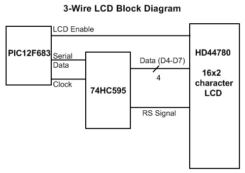
The TivaC microcontroller is frequently used in embedded systems requiring communication with peripheral devices, including shift registers. This article provides a guide on feeding serial data into the 74HC595 shift register using a TivaC.
The 74HC595 shift register is a common IC that converts serial data into parallel data. It features eight output bits that can control devices such as LEDs, LCD screens, and other peripherals. Utilizing a shift register minimizes the number of I/O pins required on the microcontroller.
To feed serial data into the 74HC595, the TivaC needs to generate three signals: serial data (DS), clock pulse (SH_CP), and latch (ST_CP).
Serial data is sent bit by bit on the DS pin. Each clock pulse on the SH_CP pin shifts the data one bit into the shift register. Once all eight bits have been shifted, a pulse on the ST_CP pin latches the data from the shift register into the storage register, making the data appear on the parallel output pins (Q0-Q7).
Configuring the TivaC pins for communication with the 74HC595 needs to be done during initialization. The three pins chosen for DS, SH_CP, and ST_CP must be configured as digital outputs. For instance, if using pin PA2 for DS, PA3 for SH_CP, and PA4 for ST_CP, the initialization code might look like this (using the TivaWare library):
// Define pins
#define DATA_PIN GPIO_PIN_2
#define CLOCK_PIN GPIO_PIN_3
#define LATCH_PIN GPIO_PIN_4

// Initialize GPIO Port A
SysCtlPeripheralEnable(SYSCTL_PERIPH_GPIOA);
while(!SysCtlPeripheralReady(SYSCTL_PERIPH_GPIOA));

// Configure pins as digital outputs
GPIOPinTypeGPIOOutput(GPIO_PORTA_BASE, DATA_PIN | CLOCK_PIN | LATCH_PIN);
After configuring the pins, data can be sent to the 74HC595 by using a loop to send each bit and generate the corresponding clock pulses.
For example, to send the value 0x55 (binary 01010101) to the shift register:
uint8_t data = 0x55;

// Set latch low
GPIOPinWrite(GPIO_PORTA_BASE, LATCH_PIN, 0);

// Send each bit
for (int i = 7; i >= 0; i--) {
  // Set data
  GPIOPinWrite(GPIO_PORTA_BASE, DATA_PIN, (data >> i) & 1);

  // Generate clock pulse
  GPIOPinWrite(GPIO_PORTA_BASE, CLOCK_PIN, 1);
  GPIOPinWrite(GPIO_PORTA_BASE, CLOCK_PIN, 0);
}


// Set latch high to update output
GPIOPinWrite(GPIO_PORTA_BASE, LATCH_PIN, LATCH_PIN);
The code above iterates through each bit of the data, starting from the most significant bit (MSB). Each bit is written to the DATA_PIN, followed by a clock pulse generated on the CLOCK_PIN to shift the bit into the shift register. Finally, the LATCH_PIN is set high to latch the data and update the output of the 74HC595.
Controlling peripherals via the 74HC595 shift register with a TivaC requires a clear understanding of how the shift register works and how to configure GPIO pins on the TivaC. By using TivaWare library functions and simple control logic, you can easily interface with a wide variety of peripheral devices.
